One of the most important parts of the structure of any building is footings or slab-on-grade support. The design and installation of these elements is essential in how the next part of the build proceeds, and ultimately, the structural stability of the whole building bearing on the ground. Failure in design or construction on these support systems will lead to cracks, sags, tilts, possibly severe damage, and expensive repair issues for any building. Needless to say, placing footings is not as simple as pouring concrete into a trench or on grade.
There are various types of footing designs — strip footings, thickened edge slab on grade, grade beams on piles, etc. Selecting the type and design involves numerous variables that demand consideration by a professional engineer or designer. Footings are basically a grade beam, transferring and distributing the building load to the soil. There are numerous factors that must be considered to evaluate this design. Variables such as the type of soil, soil bearing capacity, design loads of the wall assembly, snow loads, depth of frost, seismic zone, grade variations, and more all are taken into consideration to calculate type, width, depth, and reinforcement of the footings.
The IRC building code, free to download and view, has numerous residential design tables on footings, which take into account all these variables. To read the tables one needs to know the soil bearing capacity, snow load, the wall assembly, and number of stories. Following the tables, the size and reinforcement of the footing may be determined. The main component is understanding the soil bearing capacity and design loads for the project. Soil types have a range of different load bearing capacities per square foot.
- Bedrock – 12,000 psf
- Sandy gravel or gravel – 5,000 psf
- Sand, silty sand, clayey sand – 3,000 psf
- Clay, sandy clay, silty clay – 2,000 psf
Undisturbed soil for the footings may be measured for bearing capacity by using a hand penetrometer. This pocket-sized device is a spring-loaded probe that estimates the pressure the soil can resist and is calibrated to give readings in tons per square foot.
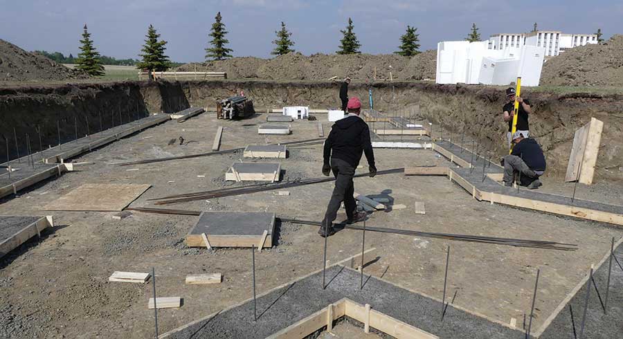
All footings, around the entire perimeter, must be excavated to undisturbed soil. The key to installing footings is to have the ability to make them level and at the correct elevation around the whole perimeter. The best practice tolerance is 1/4 inch ± of level. This may be more manageable to handle with temporary 2x formwork, installed to be level, and by using the top of the 2x formwork as the finishing elevation to trowel the concrete. There are footing formwork products and systems available. Always follow a design professional’s and manufacturer specifications.
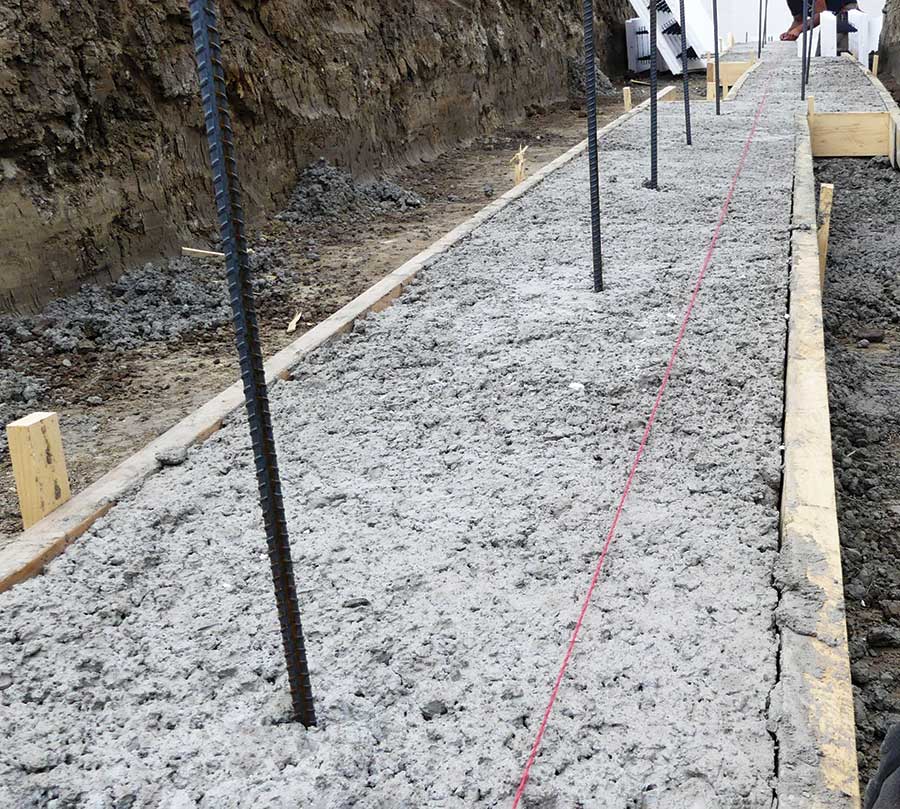
Typically, footings for an ICF wall assembly follow a similar design to any traditional residential structure. They may be similar in width and depth depending on the soil bearing capacity and building load. In some designs, horizontal rebar is not required. A best practice application is to place one or two #5 rebar to be embedded in the concrete 2 inches from the bottom of the footing, approximately 6 inches apart.
Following The Design Specifications
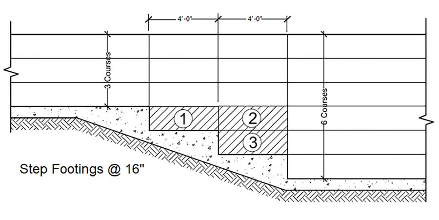
In some designs the footing may vary in elevation due to sloping grades, floors at different elevations, frost walls, etc. Any steps (change in elevation) of the footing should be made to accommodate the ICF block. Build the steps to the exact ICF block height, i.e., 16 inches or a half block at 8 inches. When using a reversible block, both parts of the cut block may be used, generally with the cut edge down on the footing. Some ICF manufacturers carry half-size blocks. Any off-size dimensions require cutting every block for that course, which consumes time, labor, and wastes material. Always design step footings to suit the selected ICF height.
The other main function of the footing is to address shear and provide lateral support to the bottom of the ICF wall. Some ICF engineering docs offer 3 alternative methods to providing this lateral support – dowels, keyway or interior slab support. The keyway is the least used application because it must be installed following exacting procedures and may cause some bulging on the top of the footing complicating the ICF install. Using the interior slab edge directly bearing on the EPS only supports the bottom of the wall from pressure or shear in one direction. Any super-imposed load on the foundation wall may be at the mid-level height causing the wall to bow inward, pushing the bottom of the wall outward, off the footing and away from the interior slab. As the simplest method, the best practice advice, is to use dowels.
This is done by inserting #4 rebar dowels a minimum of 6 inches into the center of the footing’s wet concrete, spaced typically at 4 feet on center. These dowels could be straight or have a hook in the bottom and only need to be a minimum of 16 inches high above the finished concrete. The dowels will then be embedded in the ICF wall concrete. These lateral support dowels have no relationship to the vertical rebar spacing in the wall assembly; the only goal is to provide lateral support at the bottom of the ICF wall and address shear. Plan the spacing of these dowels to not interfere with the crossties in the ICF. Dowels may also be inserted in the set concrete by drilling and using applicable epoxy adhesive.
After the footings are set (the next day), the first two courses of ICF may be placed. The next step is to level to the top of the second course of ICFs around the building. This is where the tolerance of the footing, highs, and lows, will impact the ICF. As the wall coursing increases, high spots will, at that point, make the ICFs spread apart. Low spots will make the ICF pinch together. Both scenarios influence the interlocking and placement. With the second course in place, at these problem areas, the bottom of the wall needs to either be shimmed up or trimmed down. This is a simple process but is vital to the success of the project. Once the first two courses have been levelled, the next courses of ICFs may be placed.
Some contractors, in an effort to save time and money, will attempt to place the concrete in the footings and the walls at the same time. This can be a risky venture, as the ICF walls need to be suspended and supported while the concrete is being placed. There are numerous issues that could go wrong and dealing with problems in wet concrete is never a good option. These types of applications require very experienced contractors that are willing to take and cover the risks.
Footings are a major element for the construction and support of the building. The construction and tolerances of the footings is a function that is recommended to be undertaken or supervised by the ICF installer to ensure these procedures are followed.
Project success starts at the very first stage with the footings.
Tom Patton
A 30-year architectural design background prior to joining the ICF industry in 2001 with the technical support department at ARXX. Over the last 20 years, Tom has worked with major ICF companies developing technical documentation, application details, and training programs, as well as consulting and promoting ICFs with various associations including the ICFMA, NRMCA, and codes and standards committees. Currently, Tom is Corporate Brand Ambassador for Fox Blocks and co-developer of the Fox Blocks Integrated Learning Center.


