Lessons from the British Columbia Window Buck Tests
Lab and field testing conducted over three years shows one installation method that will withstand even the worst wind-driven rain.
Many different methods (and even more opinions) exist on the issue of weatherproofing ICF walls. Only recently has the industry had solid evidence upon which to base “best practices” for window and door openings. A report issued this year by the Homeowners Protection Office titled “ICF Field Testing Report” offers a range of acceptable solutions under U.S. and Canadian building codes that address the widest possible range of building types, from single-family homes to high-rise commercial buildings.
In order to convey the findings of the report and make them easily applicable to individual projects, it is best to start at the core of the issue, which is how to permanently prevent air and water leakage at window and door openings in ICF walls. The answer begins with two basic code-compliant paths to water resistance.
Exterior Moisture Protection
U.S. and Canadian building codes typically call for a primary weather barrier (such as siding or stucco) and a secondary weather barrier (such as building paper or other synthetic membrane) behind it. This is because wood-framed walls must be kept dry to protect them from moisture damage.
Both codes contain exemptions from the secondary weather barrier in the case of above-grade masonry or concrete walls, which are recognized as a watertight plane and shed water adequately on their own.
Exterior Insulation
The expanded polystyrene (EPS) used in ICFs will not allow the passage of water or water vapor through the EPS panel, but the joints (horizontal and vertical) between ICF units can allow the passage of water, driven either by wind or gravity. This is an apparent conflict with building codes that typically require the exterior building shell to be able to shed water to the outermost plane of the wall, where it can’t harm wood framing. Not able to see concrete behind the ICF outer insulation, building officials often default to conventional wood-framed construction requirements, and expect a membrane between the building sheathing and the exterior cladding.
This is not only unnecessary, but is also unpopular among ICF proponents who object to the added costs.
Testing ICF Walls for Water Intrusion
In 2013, the major North American ICF manufacturers teamed together to provide code-compliant, tested construction details for window and door penetrations in ICF walls. They petitioned the Homeowner Protection Office to partner with them in this targeted research project. The ministry recognized the value of the research in furthering its own goal of energy reduction in the BC housing stock, and agreed to participate.
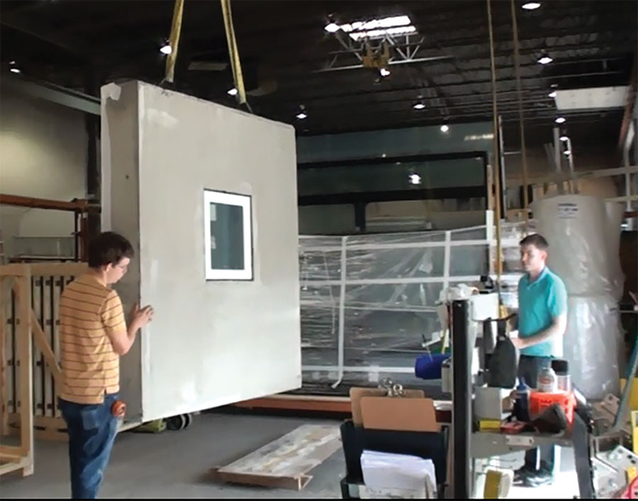
First-round testing began in 2014. Several six-foot by six-foot wall samples were constructed using six-inch-core ICFs. Each used a different buck-out method commonly in use at the time. These included various wooden bucks—some spanning the full width of the ICF wall, others recessed into the ICF cavity—as well as vinyl block-outs designed specifically for the ICF industry.
The assemblies were laboratory-tested at the Vancouver headquarters of a prominent BC window manufacturer, using their state-of-the-art air/water intrusion testing equipment. Simulated wind-driven rain, in conditions representing a wide range of building types, was pitted against a typical, fixed pane, vinyl window sample in compliance with ASTM standard E331.
The results were more instructional than encouraging. Most examples allowed water and air penetration past the assembly at relatively low levels of pressure and water flow. Some held to mid-range pressures, but all failed at the high pressure criteria levels.
With those results, the ICF technical representatives and building science experts at RDH Building Science set about designing six additional test samples with modified features or untested techniques for a second round of tests.
These yielded much improved results across the new samples, with one quite unexpected and extraordinary performance. Testing standards called for graduated pressures of 3.13 psf (pounds per square foot) [150 Pa], increasing to 6.26 psf [300 Pa], and 14.62 psf [700 Pa]. But one module was taken to 104.42 psf. [5,000 Pa] without failure. This level is seven times the average pressure criteria for high-rise building enclosures recognized in both the U.S. and Canadian codes. Even more surprising was that the ICF buckout method that was most successful was one of the simplest and least expensive for the installer.
Field Testing
Data extracted from laboratory testing was used to “short-list” four additional test assemblies for a more realistic and accurate field test under ASTM E1105. While the most successful results came from ICF wall samples featuring non-flanged (boxed or equal-leg) window frames, the ICF industry made it quite clear that a flanged window option, mounted to the exterior face of the wall, was a 100% necessity.
A technical subcommittee was formed to design a cost-effective buckout option that would both accommodate a flanged window installation and demonstrate adequate moisture and air resistance. Brian Hubbs, the lead engineer for the project at RDH Building Science, also provided input.
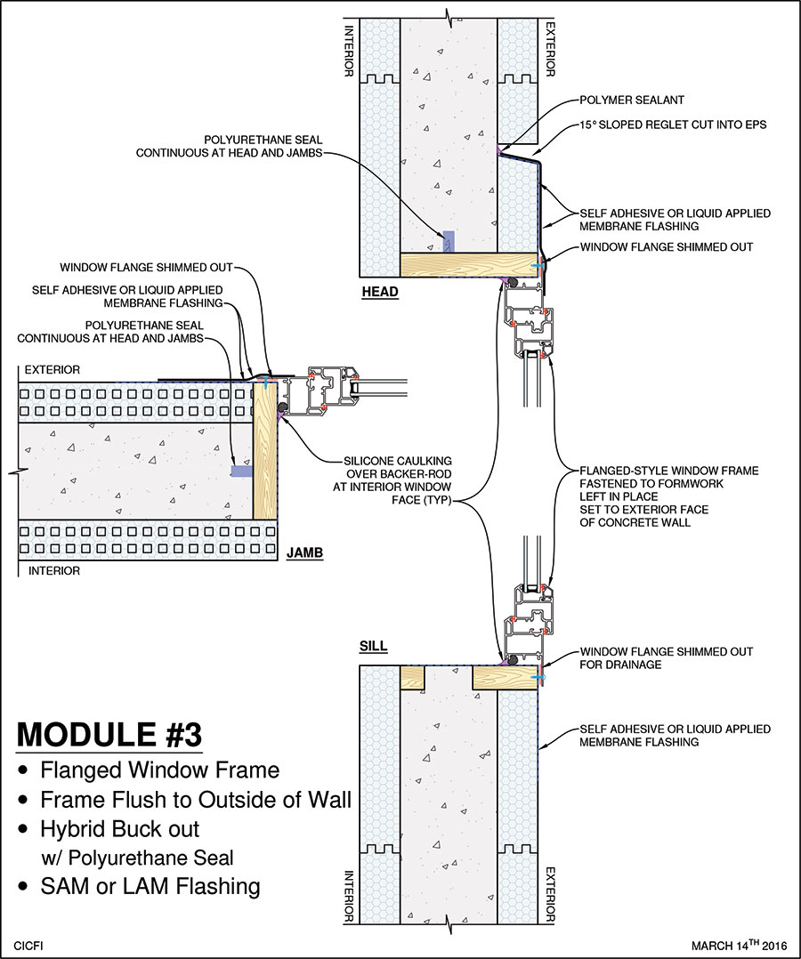
Hubbs suggested that a reglet be cut in the EPS just above the flanged window opening, allowing the head flashing from the window to be sealed directly to the concrete core. Thus, the water-tight plane of the concrete core was preserved and extended to the exterior of the flush-mounted window. The opportunity for water to pass around the extended window buckout was minimized. This method proved to be successful in the first two pressure levels tested, with minor leaks detected at the highest levels. Even though not 100% successful in testing, successful performance to tested levels exceeds requirements for nearly all residential building types in all regions.
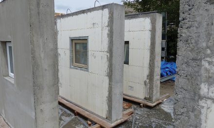
Phase 3 involved field testing. A site in Surrey, BC, Canada was selected and four more assemblies were site-constructed according to designs approved by the ICF technical professionals and building envelope engineers who oversaw the entire project. Again, the ASTM E 1105 test was conducted at varying wind-pressure and water flow levels meant to reflect conditions expected to bear on a range of building types, from single-story homes to high-rise structures.
Results for the four assemblies were as follows:
Module 1: Recessed (Internal) Wood Buckout
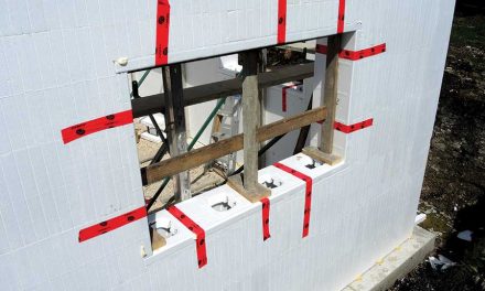
This sample used a recessed wood buckout that was left in place following pouring of concrete. This method is commonly used in ICF projects across N. America. The installation was completed with a box-framed (equal leg) window, mounted at the outside edge of the concrete core via clips fastened to the wood buck. A reglet was cut into the EPS above the window back to the concrete core. Code-mandated window flashing was applied to all sides of the window in “shingled” fashion, with the head flashing sealed back to concrete inside the top reglet. Both the interior and exterior face of the window were sealed with foam backer-rod and Dow 795 silicone sealant.
The module was successful in resisting air and water infiltration up to pressures of 6.26 psf [300 Pa], equivalent to moderate-to-severe conditions expected in low to mid-rise construction.
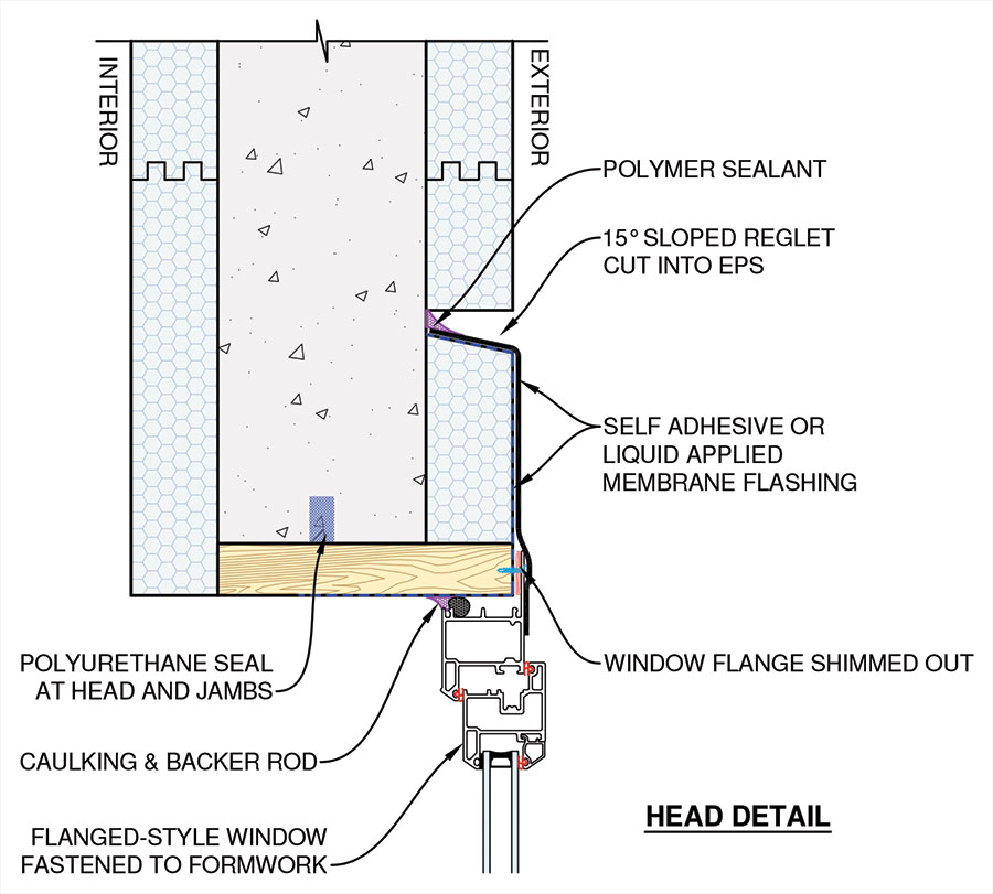
ICF wall cross-section showing flanged window installation with reglet above.
Module #2: EIFS Base-Coat
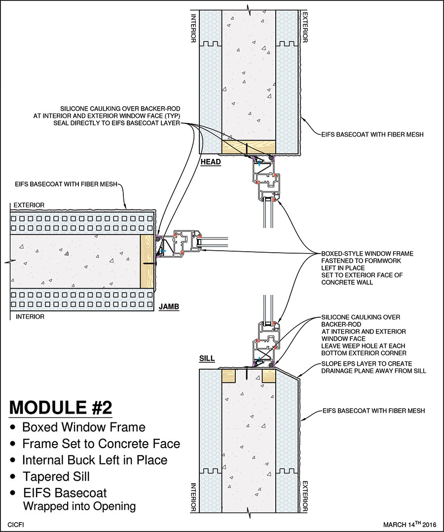
This wall section also used an internal wood buck, but an EIFS basecoat layer was wrapped from the exterior face of the ICF back into the window opening, past the position of the window. This method is common to commercial and multi-family residential buildings that are finished with face-sealed EIFS or stucco systems. A box-framed (equal leg) window was positioned at the exterior face of the concrete core. Again, the interior and exterior face of the window were sealed with foam backer-rod and silicone sealant.
This module withstood twice the air and water infiltration pressure of the first sample (14.62 psf [700 Pa]) equivalent to the most severe conditions expected to act on high-rise construction in any building use category.
Module #3: Hybrid Wood Buckout with Flanged Window
This sample used a flanged window attached to a wood substrate, flush to the exterior face of the ICF wall. This method is common to low-rise residential buildings finished with either face-sealed (stucco) systems or a variety of cladding options, and was deemed as critical by the ICF stakeholders. A flanged window was fastened to the outer face of a permanent wood buckout at the exterior face of the EPS. Code-mandated window flashing was applied to all sides of the window in “shingled” fashion, with the head flashing sealed back to concrete inside the top reglet. Only the interior face of the window was sealed with foam backer-rod and silicone sealant (Dow 795).
The module was successful in resisting air and water infiltration up to pressures of 6.26 psf [300 Pa], the same as the first sample tested in this phase.
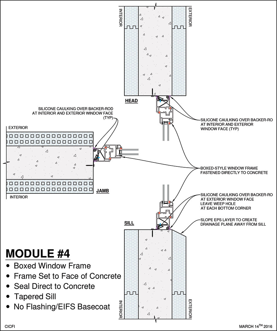
Module #4: Window Sealed Directly to Concrete Rough Opening
In the fourth sample, the buck was stripped after the pour, leaving the concrete core exposed. This method is common to commercial and multi-family multi-story buildings of any height. A box-framed (equal leg) window was positioned at the exterior face of the concrete core. Both the interior and exterior face of the window were sealed with foam backer-rod and silicone sealant directly to the concrete core.
Since the concrete core is providing 100% protection, no exterior window flashing was required.
This assembly was by far the most successful at resisting water and air infiltration. After having successfully resisted pressures in laboratory testing of 104.42 psf [5000 Pa]. the field test module was successful in resisting air and water infiltration up to pressures of 14.62 psf [700 Pa]. This is extraordinary. This is equivalent to wind speeds of more than 500 mph, conditions that don’t even exist on this planet (maybe Jupiter), and the ICF wall/window assembly was proven 100% tight in such conditions. In the opinion of the author, this is a game-changer.
This option is not only the most effective at preventing air and water intrusion, but because it doesn’t need flashings, it is also the lowest cost option for installers.
Bottom Line for the ICF Industry
As an initial step, results presented in the Homeowner Protection Office “ICF Field Testing Report” will guide the formulation of new “best practice” construction details for ICF buildings in the upcoming revision of the BC HPO “Building Envelope Guide”. Other Canadian provinces will likely be considering the information published in British Columbia as they develop their own future guidelines.
As U.S. building codes continue to evolve, the ICF industry will offer guidance to the International Code Council, similar to that offered during formulation of earlier ICF Acceptance Criteria AC-353. This effort will include the ICF construction details developed as a result of BC HPO research.
From an ICF Industry perspective, this third-party research fosters a major step forward in its ability to offer proven, cost effective solutions for code-compliant, high-performance building design across a broad range of building types and uses, in the MOST extreme conditions. Add to this the structural & fire capacity of reinforced concrete structures, the entire resilience picture begins to quickly gel. Design professionals can now rely on an even broader range of features brought to the table by ICFs and concrete.
Douglas Bennion is the manager of training and technical services at Quad-Lock Building Services, Ltd. He was instrumental in all phases of the research project reported above.
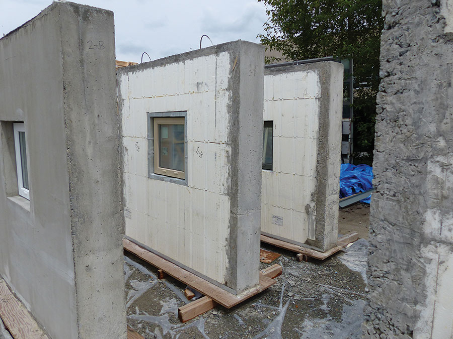
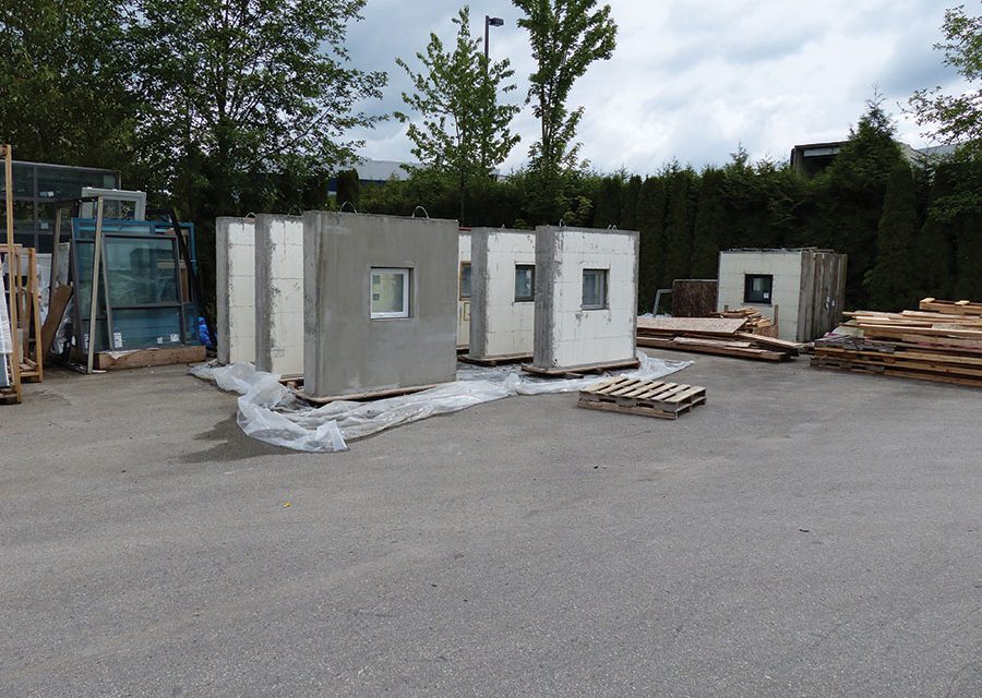
A total of 16 wall samples, each with a different buckout method were tested. The best sample withstood pressures equivalent to 500 mph winds.







Hi very interesting article I am curious about the thermal transference from the concrete used in the fourth method. It seems that there might be an issue where the window meets the concrete and allow transference to occur. If one were to use icf bucking that fit in between the inner and outer icf panels and then removed the wood bucking are you still able to install replacement type windows without flashing?