The genius of the insulating concrete form (ICF) stems from the complementary strengths of the three primary materials used: EPS Foam, steel, and concrete…
The foam provides the insulation; all of the structural strength comes from the reinforced concrete.
Unreinforced concrete can carry very heavy compression loads, but is relatively weak under tension. To compensate, steel reinforcing rods, commonly called rebar, are added.
The idea was invented independently by several men in the 1800s. Joseph Monier, a Parisian gardener who made garden pots from concrete reinforced with an iron mesh, is generally given credit. Several decades later, Ernest Ransome began using twisted iron bars in multi-story concrete construction. More than a century has passed since then, but ribbed steel bars remain the material of choice.
Wikipedia explains why: “While any material with sufficient tensile strength could conceivably be used to reinforce concrete, steel and concrete have similar coefficients of thermal expansion, resulting in less stress during temperature changes.”
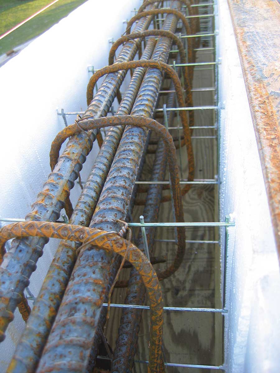
Lintels require closely following the engineer’s specifications and careful vibration to ensure consolidation.
Today, construction codes require that every concrete wall have some amount of structural steel. But the amount required, and its location in the wall, varies widely.
Ian Giesler, who has built dozens of ICF projects across North America, states, “Reinforcing requirements differ from one extreme to the other, from Maine to California and all places in between. Yet one thing is common: when ICF use moves from one and two family dwellings to commercial, institutional and other types of structures, reinforcing steel significantly impacts the time, cost and the manner in which the walls get installed.”
Of even more concern is that even in the same city, two engineers may specify vastly different amounts of rebar. It seems ICF construction is especially prone to “over-engineering,” which can have a significant influence on the final cost of the project.
The purpose of this article is to outline some basic guidelines for placement of structural steel in ICF walls. Because the vast majority of the industry uses monolithic “flat wall” systems, it only addresses these walls. Screen-grid and waffle-grid systems are beyond the scope of this article.
Published Standards
The most important rule to remember is ICF walls require the same amount of rebar as walls cast with removable forms. The American Concrete Institute (ACI) has published extensive research on the topic (notably ACI 318), as has the Portland Cement Association (PCA), the NAHB Research Center, and others. The sidebar at right details a few of the most widely used references.
ACI 318-08: Building Code Requirements for Structural Concrete and Commentary, American Concrete Institute; 2008; 467 pages;. Available from ACI Bookstore.
Design Criteria for Insulating
Concrete Form Wall Systems, Portland Cement Association; 1996; (out of print).
In-Plane Shear Resistance of Insulating Concrete Form Walls, U.S Dept. of Housing and Urban Development (HUD); 2002; 48 Pages; Available through the NAHB Research Center Bookstore.
PCA 100-2007 Prescriptive Design Of Exterior Concrete Walls for One and Two Family Dwellings, Portland Cement Association; 2007; 244 pages. Available from
PCA Bookstore.
Prescriptive Method for Insulating Concrete Forms in Residential Construction, 2nd Edition, U.S Dept. of Housing and Urban Development (HUD); 2002; 198 Pages; Available through the NAHB Research Center Bookstore.
Testing and Design of Lintels Using Insulating Concrete Forms, U.S Dept. of Housing and Urban Development (HUD); 2000; 38 Pages; Available through the NAHB Research Center Bookstore.
Structural Design of Insulating Concrete Form Walls in Residential Construction, Portland Cement Association;1998 ; (out of print).
Giesler notes, “Publications such as PCA 100-2007, Prescriptive Design Of Exterior Concrete Walls for One and two Family Dwellings, have given the industry a general engineering manual that is included in the residential building code. This manual not only provides and explains details and calculations for reinforcing placement, it is from a credible and legitimate resource that is accepted by the construction industry. The Prescriptive design is undoubtedly one of the most valuable contributions to propelling ICF into the mainstream in the residential construction market.”
Robert Klob, an Arizona-based home designer with extensive ICF experience cautions, “Many times builders, architects and designers will use the prescriptive method in order to save money on a project in the beginning. There is really nothing wrong with this method as long as you understand [that] the prescriptive method only takes into consideration very basic variables. I have found on numerous occasions it would have actually cost my client substantially less money during construction had we hired a structural engineer.”
A custom-engineered building will take into account seismic, wind, and roof weight loads, soil conditions, and other items so that each section of wall is designed to accommodate the forces it will actually face. Walls that have higher loads are designed for such. Walls that don’t have substantial loads will have less mass and less steel reinforcing, thus saving money during construction.
Custom Design
Robert Oleck, regional director of McLaren Engineering Group, is a professional engineer and PhD that has designed steel reinforcements for several significant ICF projects in Florida.
He warns, “For experienced concrete design engineers encountering ICFs for the first time, they will find that the design process for ICF does involve additional considerations outside of the criteria normally considered for conventionally poured-in-place concrete walls under ACI 318, particularly chapter 14.”
The biggest difference Oleck mentions is the spacing between horizontal rebar. “ICF form manufacturers include an embedded form tie which holds the horizontal reinforcement. ICF forms are manufactured at various heights ranging from 12”, 16”, 18” and 24”. Therefore, the vertical spacing of horizontal reinforcement can vary depending on the ICF form used.”
Basically, it’s easiest for installers if the horizontal rebar spacing matches the height of the ICF form being used.
“To be in concert with the particular ICF, horizontal reinforcing spacing should be based on an increment equivalent to the height of the form unit,” Giesler says. “This approach allows the installer to take advantage of the reinforcing holders that are built into the formwork and increase productivity.”
Because most ICFs are 16” tall, the most common horizontal spacing of reinforcing is based on an increment of 16”. If the preferred brand of ICF is 12” or 24” inches high, be sure the engineer is aware of this fact. Otherwise, the steel has to be slid into place from the end of the wall and laboriously tied by hands.
“When the design engineer specifies a reinforcing spacing that is out of sync with the form system of choice, the best solution is to provide the engineer with backup information and a request to change the spacing to work with the system,” Giesler says.
For instance, if the plans call for bars 24” on center, and the ICF is only 16” tall, there should be three options: (1) Use a thicker bar every 32” (2) Use a double mat of rebar at 32” (3) Install the rebar at a closer-than-specified distance of 16” on center.
“Changing reinforcing schedules is usually a difficult task since it requires changing specifications which is not so easy once the engineer has been paid for the design work,” Giesler warns. “Requesting to decrease the spacing of reinforcing is usually easier to do without significant issue from the designer team. Additional reinforcing will negatively impact reinforcing steel costs but will likely create savings to the installer’s time, so there is a tradeoff.”
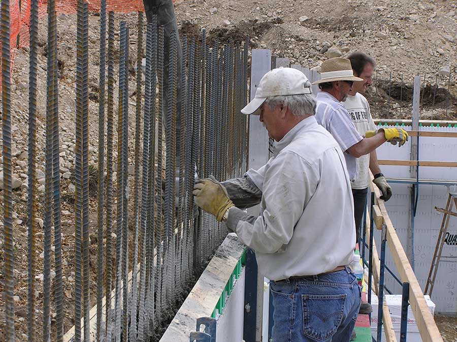
In areas of the Rocky Mountains and Pacific Coast, double mats of rebar are frequently specified. Minimize hassles by ensuring the design matches the vertical and horizontal layout of the ICF web ties.
Vertical steel specifications also are impacted by the chosen form system. It’s most convenient if the distance between vertical rebar is a multiple of the web spacing in the ICF (usually 6” or 8”).
The key to dealing with steel schedules that don’t match the dimensions of the form of choice, Giesler says, is to “move quickly, provide alternate design layout, and ask for acceptance of a criteria that will be conducive to the form of choice.”
All of the major ICF manufacturers have engineers and/or technical directors on staff that will be happy to help out. “Most design professionals will accommodate minimal change,” Giesler says. “They have an interest in the form installation going smoothly.”
Securing Steel
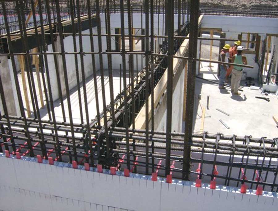
ICF manufacturers are continually trying to improve their product, and rebar saddles are one area where this really shows. New designs have built-in horizontal rebar holders on the web ties that securely locate steel with precision. In many brands, the reinforcing steel actually snaps into the web, eliminating the need to tie the steel into place.
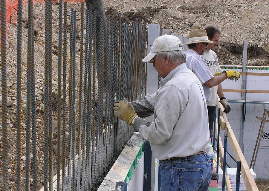
They’ve also created simple methods for inserting vertical steel. Quad-Lock, for instance, recommends sliding a short piece of small-diameter plastic pipe over each of the dowels protruding from the footing. After the wall is in stacked, the vertical rebar is snaked into the wall from the top and nested inside the pipe. In some jurisdictions, this is adequate without any additional tying.
In any case, Giesler estimates that advances in web tie design have easily cut reinforcing steel placement times by half when compared to older ICF models that require manually wiring the reinforcement in place.
Congested Steel
Most of the complaints about “over-engineered walls” come from builders on the West Coast. That’s because the seismic and wind load criteria for most of the region require walls that are designed “steel heavy.”
Lintels over large windows and doors frequently have congested rebar. These areas require special care during the pour.
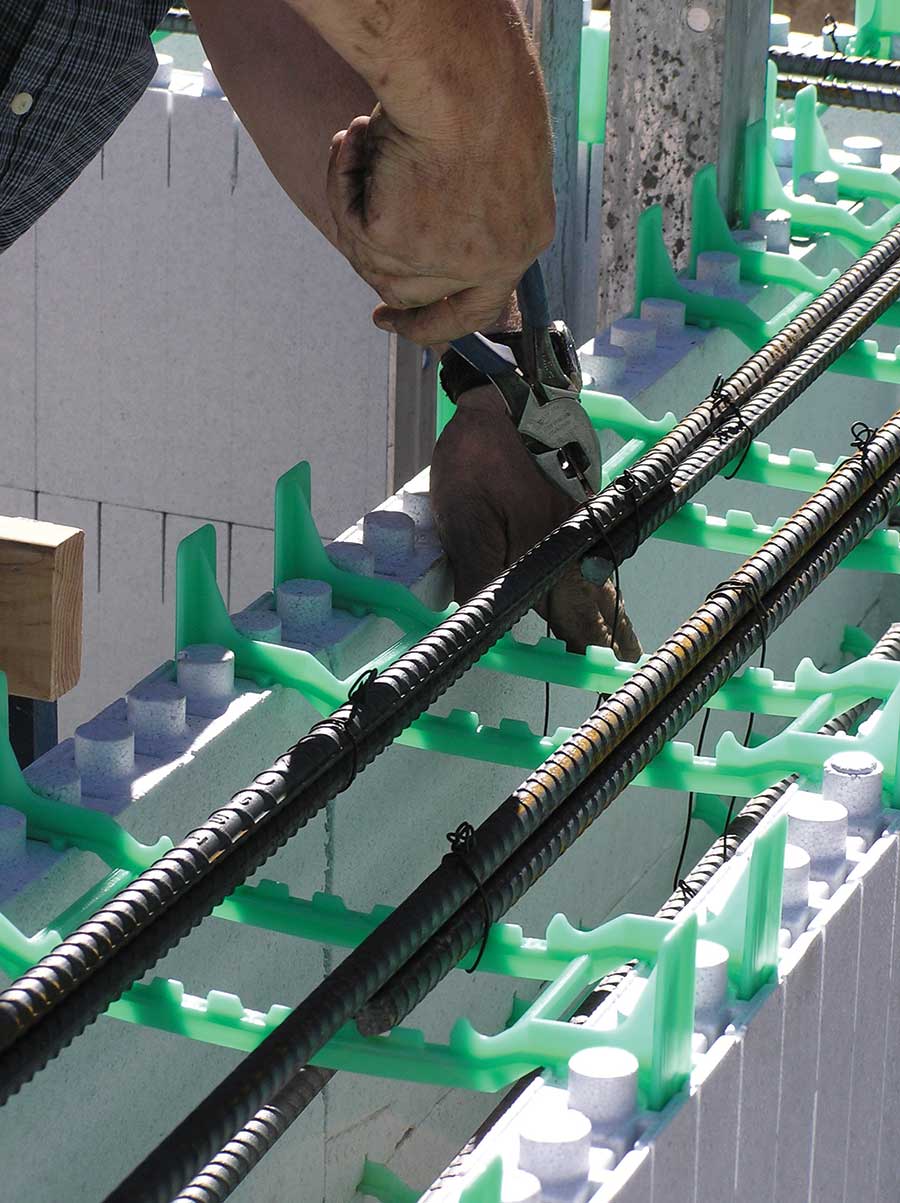
A few forms require steel to be tied to the plastic webs. Newer forms eliminate this task with holders that snap the rebar into place.
“Large volumes of reinforcing not only impacts the time of construction, but adds another complication,” says Giesler, “consolidation of the concrete around the steel and webs of the formwork.” A good engineer will design the steel spacing to complement the webs. Giesler adds that communicating with the batch plant to create an easily consolidated mix design can make a potentially time-consuming install much easier.
In cases of extremely tight rebar, panel-type “knockdown” ICFs offer significant time savings during installation, as they allow each side of the wall to be constructed independently. A few systems, such as IntegraSpec and the vertical ICF designs, allow for easy inspection of the steel after the wall has been erected.
As always, proper vibration is a must. Modern ICFs hold up extremely well to “pencil head” vibrators. Oztec markets a device that turns the rebar itself into a vibrator. Called the Rebar Shaker, it slips over the top of the rebar and consolidates the concrete into a solid void-free mass in seconds.
Minimizing Costs
With any construction job, cost is a major factor. Keeping the cost of structural steel to a minimum while providing the required level of strength is part of that. Klob often recommends engineering the building instead of blindly following the prescriptive method. In one case, he was able to save the client over $75,000 by decreasing the amount of concrete and steel in the wall.
ACI 318 section 14.3.5 requires that “Vertical and horizontal reinforcement shall be spaced no farther apart than three times the wall thickness, nor farther apart than 18 inches.” ACI standards also state that steel can be no less than .02% of the wall volume. But Oleck, the professional engineer, explains that additional considerations exist which may relax these requirements.
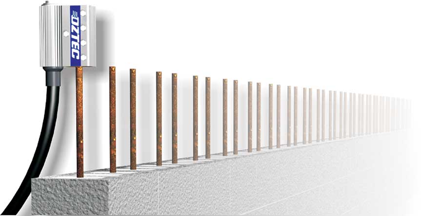
Oztec’s rebar shaker turns the steel itself into a vibrator, which can be a lifesaver in areas of congested rebar.
“The first,” he says, “is the fact that in many cases, unreinforced concrete is capable of resisting forces, especially if the resultant stresses are primarily compressive.” He says ACI 318 Chapter 22 section 22.6 allows for the design of plain concrete walls if:
1) The total of all factored loads is located within the middle-third of the overall wall thickness, and
2) The walls are supported in such a manner as to prohibit relative lateral displacement at top and bottom of individual wall elements.
Oleck adds, “In moderate design wind speed areas and seismic zones, the wall cross section is primarily in compression and requires only minimal reinforcement for temperature and shrinkage considerations.”
Additionally, even the ACI code allows for an engineer’s judgment in applying ACI 318. Section 14.2.7 states, “The quantity of reinforcement and limits of thickness required by 14.3 and 14.5 shall be permitted to be waived where structural analysis shows adequate strength and stability.”
In 1996, John Roller authored a study for the PCA titled Design Criteria for Insulating Concrete Form Wall Systems. He concludes, “based on review of the ACI index, which dates back to 1905, no papers have been published by [ACI] which deal specifically with this [horizontal reinforcing in concrete walls]. Therefore, it appears that existing code provisions for minimum quantities of reinforcing steel are based solely on engineering judgment and have no apparent technical basis.”
Testing performed by PCA for ICF wall systems concluded that 48” on center spacing for both horizontal and vertical reinforcement is an adequate minimum.
Cautions
Of course, the 48” minimum mentioned above would be ludicrously inadequate on the West Coast. That’s why engineers and designers must be sure their designs are adequate.
In addition to compression loads, the engineer must also to ensure that the appropriate requirements of vertical and horizontal shear have been met by the design. Finally, the wall should also meet flexural requirements as specified in ACI 318 Sections 10.5.1 and 10.5.2.
The final design must be stronger by 1/3 than the greatest load calculation.
But, Oleck says, “as long as the horizontal reinforcing is at least 33% greater than that required by structural analysis, the strict adherence to the .02% rule established under 14.3.3 and 10.5.1 may be waived.”
He cautions, “It should be understood however that the engineer needs to be careful where some walls span horizontally—not vertically—depending on the location of intersecting walls and type of loading when considering this calculation.”
In any case, all plans must be stamped and approved by a licensed professional engineer certified in the local jurisdiction.
Properly engineering an ICF wall can save money and speed installation. However, the structural integrity of the wall is always paramount. By following the guidelines outlined above, it should be possible to achieve all of these aims.










You provide good and accurate information. Thank you to all that takes time out to give back information to those seeking help. You all are Awesome!