The thermal performance of insulated concrete form (ICF) walls has been a long-debated topic amongst building industry leaders.
ICF companies have touted their performance while cavity wall proponents have argued that their superior performance is purely anecdotal. In 2017, the Insulated Concrete Forms Manufacturing Association (ICFMA) chose to seek hard data behind anecdotes to explain the thermal performance of ICF wall assemblies.
To comprehend the full story, one must first understand the historical code transition for mass walls that transpired between the 2009 and 2018 code cycles. In the 2009 IRC/IBC, mass walls could use less overall insulation in comparison to cavity wall assemblies. This decision was made because mass walls contributed an enhanced benefit to the performance of the wall. This caveat in the code came out of research that was conducted in the 1990s and early 2000s.
One important study that the ICF industry cites was conducted at Oak Ridge National Laboratory called the Dynamic Thermal Performance of Concrete and Masonry Walls. The study modeled several uniform concrete structures with mass walls and four different insulation configurations—on the inside, outside, both sides and without insulation—in several different climate zones. Control groups were established and cross tested with modeled calculations used in the software against actual hot-box data collected from several of the assemblies. The results found that structures with insulation on the outside of the mass wall performed better than some of the other configurations.
A later study at Oak Ridge National Laboratory confirmed these results and went further to compare the results to cavity wall performance. This study, Influence of Building Design on Energy Benefit of Thermal Mass Compared to Prescriptive U-Factors, confirmed the enhanced performance of mass walls with insulation on the outside and further validated that mass wall performance was superior to cavity wall construction.
Research such as these reaffirmed the 2009 ICC decision to allow less overall insulation for mass walls and demonstrated that continuous insulation on the outside of structures is one of the best ways to improve the energy performance of buildings, especially those in colder climate zones. Continuous insulation reduces the effects of thermal bridging. When looking at the 2012 and 2015 IRC/IBC, similar research was applied to cavity wall construction resulting in continuous exterior insulation along with air barriers becoming an acceptable practice to improve the performance of framed walls.
In recognition of this changing market dynamic, the members of the ICFMA joined to commission independent rigorous testing of ICF wall assemblies. The first study, called the CLEB Study, evaluated the performance of an ICF wall assembly compared to a code-compliant 2×6 cavity wall assembly. This study confirmed not only the performance contribution from continuous insulation, but demonstrated that mass walls performed significantly better than cavity walls with batt insulation. (See “New Study Quantifies Thermal Mass Benefits” in the May 2017 issue.)

After evaluating these results, the ICFMA commissioned two additional studies evaluating an ICF assembly in comparison to several different wood and steel-framed cavity assemblies; especially assemblies that use continuous insulation. The next study solicited CAN Best Laboratories in Ontario to conduct a series of guarded hot-box thermal tests to compare ICF wall performance with cavity wall assemblies that are currently in use and code compliant in both USA and Canada. The assemblies tested are shown in Figure 1. For the third study, ICFMA solicited RDH Building Science Laboratories to examine the airtightness of existing ICF structures using blower door technology to test the air changes per hour (ACH) performance of existing ICF structures in comparison to a large body of research conducted on structures built with wood-framed
cavity walls.
CAN Best created a guarded hot box test by placing a wall section without windows inside a sealed chamber, with the wall assembly splitting the chamber into two distinct sides. One side of the chamber blows continuous hot or cold air, mimicking outdoor elements, while the other side with a calorimeter is kept at a constant controlled temperature, mimicking an occupied home. To test the performance of an assembly in cold weather, the blowing side has a temperature of -31º F and the controlled side has a controlled temperature of 72º F. To test the performance of an assembly in hot weather, the temperature on the blowing side is 131º F and the controlled side is 72º F. Temperature gauges were placed in the wall assembly to monitor any temperature fluctuation throughout the wall during the experiment.
Once the test is begun, air is blown at a continuous rate at the stated temperature and additional energy is added to the temperature-controlled side to keep it at a constant temperature of 72º F. The temperature in the wall is then continuously measured until it no longer changes temperature. The controlled side is also monitored to find a state of equilibrium where a fixed amount of energy can be applied to maintain the temperature of the chamber and wall. This point in the experiment is called steady state and allows for several calculations to be made. The first value is a calculation of R-value. The second is the amount of energy input that is needed to maintain equilibrium. The amount of time it takes for the experiment to arrive at steady state is also noted.
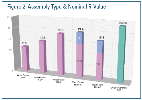
Five total assemblies were tested in heating mode, and a sixth data point was added from the prior CLEB study. Figure 2 shows the calculated results of the R-value of each assembly at steady state. Every cavity wall tested performed worse than the expected R-value based on the materials used in the assembly. For example, the cavity wall with R-20 batt insulation might have been expected to perform at or near an R-20. In reality it performed closer to an R-14.8. On a percentage basis this is nearly 25% less overall R-value. The ICF wall however, performed at or slightly better than its material basis. In the test case, the assembly performed at an R-23.36 when its actual R-Value is an R-23. This result shows that thermal bridging is still a significant problem for cavity walls. Even when continuous insulation is used on a cavity wall, it is still unable to achieve a comparable performance to an ICF wall. The study also confirms that the steel stud wall, which comprises a significant amount of commercial construction, performs worse than an equivalent wood wall.
At steady state, the total energy input into the controlled side of the wall was calculated. When an assembly can achieve a higher R-value, less overall energy is needed to maintain a stable temperature. Over the duration of the experiment, total energy usage is also calculated. Since the ICF wall slowly moves towards steady state, it consumes significantly less energy over the same time period. For the end customer, this translates into actual savings on heating or cooling bills, and additional cost savings such as allowing the reduction of the HVAC equipment used in the structure.
The last data set that can be pulled from the research is the amount of time it takes for a wall assembly to move towards steady state. See Figure 3. In heating mode, most assemblies move towards steady state in 12 hours or less. This means that when a cold front moves through a region, a wood or steel structure will quickly need energy to keep the building at a stable temperature. The structure becomes little more than a sophisticated tent. In contrast, an ICF wall dramatically resists temperature change, due to stored energy in its mass. While the best built cavity wall with continuous insulation was able to achieve a steady state time of 54 hours, it pales in comparison to the result of the ICF wall at 144 hours.
The time to steady state data confirms the enhanced benefit argument. The stored energy in a mass wall acts like a thermal battery. The wall temperature in the concrete trapped on both sides by EPS insulation changes its temperature very slowly. This partnership allows the wall to resist major temperature swings in the environment. Additionally, because of the ICF’s airtightness, a structure will retain its warm or conditioned air much longer. In a power outage situation, an ICF structure will be significantly more resilient. Douglas Bennion, chair of the ICFMA technical committee suggests, “An ICF structure gives an ‘ART,’ advanced response time, which means you can shelter in place for longer periods of time during a power outage or extreme climate event.”
The third study by RDH Laboratories examined the air tightness of 49 ICF structures in comparison to blower door data collected on nearly 230,000 wood structures throughout the US and Canada. They additionally took data sets from a prior ORNL study and MIT study on the airtightness of ICF structures to compare with the new research results. In summary, they found that wood structures built between 2002 and 2012 had an average ACH rating of 4.8, while the ICF structures studied had an average ACH rating of 1.26. This performance confirms that a monolithic concrete wall with insulation on both sides significantly improves the air tightness of a structure. As building codes are evolving, the focus is shifting to the control of unregulated air flow through the building shell, rather than increasing the amount of insulation. Insulation in terms of contribution to the thermal envelope is considered less important than air intrusion. ICF walls have been shown to eliminate unregulated air flow in clear-wall areas, leaving only doors, windows and other connections to contend with.
When these studies are used in conjunction, they demonstrate the effectiveness of an insulated mass wall. As the building science community continues to search for more energy efficient building materials, it should be noted that ICF walls demonstrate a strong historical track record. They perform better than cavity walls, maintain their R-value over time, and consistently resist temperature fluctuation because of stored energy. ICF structures require less overall energy to heat or cool, and the longer time required to reach steady state “flattens the temperature curve” delivering safety, comfort and less cost to the end user.
Micah Garrett is chair of the ICFMA education committee and COO at BuildBlock Building Systems.