By Dave Gowers
Building walls with ICF is a tremendous step in the right direction to create an almost fire-proof enclosure. But so much more can be achieved by building a complete concrete envelope.
As I sat here in Oregon, writing this article, Southern California was burning. The incredible devastation of fire that spread through Pacific Palisades, and the surrounding areas, has destroyed thousands of buildings, caused the death of 30 people, and displaced about 150,000 people. The whole western seaboard is vulnerable to fires for the foreseeable future. This begs the question — why are we still building so much with wood-framed construction? For those who have seen the folly of this method of building, ICF construction has become the obvious alternative. A 6-inch concrete core has a fire rating of 3 hours, and while nothing is 100% “fireproof,” ICF is certainly substantially fire-resistant.
Building walls with ICF is a tremendous step in the right direction to create an almost fire-proof enclosure. But so much more can be achieved by building a complete concrete envelope, by constructing the roof also with a concrete-based system. This is more achievable than it sounds. The natural repose angle of 4-inch slump concrete is around 17 degrees. That’s the angle at which wet concrete begins to slump if it were in a heap. As it happens, that is really close to a roof slope of 4:12. Many roofs in Southern California are at that roof pitch, so there could be many opportunities to completely rebuild with concrete. There are two principal types of lateral forming systems used in ICF construction — each is described in detail below.
Lateral Foam-based Systems
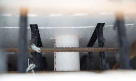
Foam-based lateral systems are one type of lateral system used in ICF construction. These include forming systems like Insul-Deck, Quad-Deck, Amdeck, LiteDeck, BuildDeck, and Fortruss. This is not meant to be an exclusive list, and I’ve no doubt there are several more systems available not mentioned here (see Decking Chart on https://icfmag.com/icf-comparison-chart). All these systems effectively form a concrete T-beam joist matrix, and the foam form stays in place. The tail of the T-beam is typically at 24-inch spacing and is connected to a structural topping slab of 3 to 4 inches in thickness. Shear transfer is created through embedded rebar dowels, and the result is a very stiff lateral concrete diaphragm.
These systems may be used for truly horizontal applications, such as floors and flat roofs, but can also be used for sloped roofs. For up to a 4:12 roof application it is only necessary to slope the system to the required pitch and carefully place the concrete. Slump control is important, as it should be maintained between 3 inches and 4 inches. Fortunately, modern boom concrete pumps can accommodate these lower slumps, but it is still necessary to keep good control of the concrete slump.
Roofs with increased pitch can still be formed, but the introduction of a top form is normally necessary. This can be done by securely fastening a modular ICF system over the foam-based lateral system so that you are now placing concrete within a sloped ICF wall in addition to the lateral foam system. I have used this technique successfully to design several steep ICF roofs, up to a 12:12 pitch!
In all cases, lateral foam-based systems require temporary shoring. This is typically a post-supported stringer system, running perpendicular to the T-beam direction, and spaced depending on the combined dead and live load for the application. A spacing of 6 feet is usually the maximum. For more than a single story of the same construction, reshoring may be necessary for the lower floors. The ICF structural engineer should also provide design services for the complete temporary shoring and reshoring system.
Metal Joist Lateral Systems
There are several metal joist-based lateral forming systems. These include systems such as Ecospan, TotalJoist, Super Joist, and Super Floor. Again, this is not meant to be an exclusive list as I’ve no doubt there may be several other similar systems not mentioned here. The joists for these systems may be placed up to 5 feet spacing, spacing dictated by span and overall floor depth. The joists are topped with a pan deck form, which can support the weight of a topping slab which typically would be 3 to 4 inches deep. The topping slab connects to the joists through shear connectors, and when hardened, creates a composite concrete diaphragm.
The metal joist-based systems differ from the foam-based systems in several ways. The most significant difference is that they typically do not require temporary shoring. They are designed to span freely between the permanent support members, whether those support members are walls or beams. This eliminates the cost of temporary shoring and reshoring, which can add up to a significant cost in both time and expense.
The foam-based systems keep the foam in place when all concrete is poured, whereas with the joist-based systems, insulation has to be added after the fact. This can be in the form of batting or rigid foam.
The metal system joists have solid webs, with ports, or are of a lattice web design. Both these styles allow for utilities to be placed through the joists without the need for additional modification of the structural elements. Foam-based systems are less user-friendly in this regard and need more pre-planning.
Floor construction is no problem with metal joist-based systems, especially as they eliminate the need for temporary shoring. This equally applies to roof applications, but a roof pitch of 4:12 is the practical limit for these systems. Applying a top form is problematic, hence the 4:12 pitch restraint.
Speed of Construction
Typically, both systems are installed in approximately the same amount of time, even allowing for the added time factor associated with temporary shoring. Temporary shoring and reshoring can, however, interfere with following trades, so this needs to be taken into consideration, especially for commercial construction.
Conclusion
There is much to be gained using one of the ICF-friendly lateral forming systems described above. By creating a complete concrete envelope, the resulting increase in fire resistance, structural stiffness, and consequent seismic resistance, is significant. I truly hope for some good to derive from the devastating California fires, and that future building codes will embrace increased fire-resistant construction.
Dave Gowers
After graduating from UK’s London University in 1969, Dave Gowers acquired extensive experience in concrete construction, through a diversity of commercial, residential, and industrial projects, up to $1 billion in value, and in several countries. He is well-versed in concrete formwork and shoring systems, and over the past 20 years has produced structural design solutions for over 200 ICF projects, both residential and commercial. Dave resides in Southern Oregon with his wife and business partner, Jennifer. Dave holds a PE license in 15 states/territories, is the principal of Dave Gowers Engineering LLC, and is the co-principal of Cascade ICF LLC. His website is www.dgengineering.com and he may be reached at 541-660-9661 or
dave@dgengineering.com.


